PHOSPHORM MANUAL

Oscillographics is a colloquial term for any usage of an oscilloscope for creative purposes! Basically its poorly defined and fairly arbitrary. If I’m testing a circuit or monitoring a waveshape while doing sound design it might not be considered oscillographics. On the other hand if while I’m monitoring a waveshape and I stumble into something that looks really neat and I decide to focus more on the visual aspects then I’m definitely doing oscillographics at that point. Like many artistic definitions it can seem vague,imprecise, and not really worth debating unless yr thesis depends on it lol.
(TECHNICAL DISCLAIMER: like pretty much every engineering aspect of video art, the technical details of whats going on with signals and hardware can get pretty intensely occult real fucking quick when u start to dig into them. I’ll allude to a lot of things that I won’t explain here and to be quite honest some of what I’m saying is not stricly true in operation but is kind of ‘ecstactically true’ in the herzogian sense for someone with little to no knowledge of the science and engineering behind the signals and hardware to get a useful intuition on how to work with these as a creative medium! To make an oil painting you don’t actually need to understand all of the physics and/or optics, but it definitely helps to have an intuitional understanding of how linseed oil and pigments interact with regards to specularity, opacity, blending, layers etc in order to do crazy and fun stuff with the medium!)
WHAT IS VECTOR SYNTHESIS?
This is a tiny bit more rigorously defined! Not going to make it into any mathematics textbooks any time soon but you could probably fit it into an engineering textbook in like an appendice or something! This is not an engineering burn, I myself would consider most of what I do to fall into an incredibly fun intersection of Mathematics, Computer Science, Engineering, and Art. If I wanted to get even more pathological about intersctions I’d most likely have to add some kind of Psychology/Biology in there as well to cover the research that I do on Sensation and Perception in the human nervous system! All strict divisions between studies are inherently false and mostly an unfortunate byproduct of modern western academic thought processes! Down with the Ivory Carpet!
ok anyway

Vector synthesis is a form of video synthesis that utilizes a special kind of oscilloscope that uses at least 2 seperate inputs for generating visuals. How the heck can we use 2 seperate signal inputs to generate 1 video signal? To explain this we will first want to understand how the cathode ray tube of an oscilloscope differs from that of a television set.
In a North American cathode ray television set we have a fixed frame (actually called a field but fuck if I want to get into interlacing at this point) rate of 60hz or 60 times per second. Why 60? Probably because of Chaldean mysticism! And also because of North American alternating current alternating at 60hz. So for each individual frame there is an electron gun which scans from a fixed point in the upper right hand corner sequentally down to the lower left hand corner much in the same way that the english speech is written and read.
For every pixel in between the upper right hand corner and the lower left hand corner the electron gun shoots an electron with an intensity which results in the brightness of the pixel! (lets ignore color too, if you think interlacing is complex wait’ll u learn about quadrature amplitude modulation). The important thing to note here is that no matter if I have a video signal which is mostly black or even entirely black (meaning no electron is shot out at the screen) the gun is still moving in this fixed pattern from upper right hand to the lower left hand
Seems potentially ineffecient no? Why don’t we just have the electron gun ONLY scan and shoot where we actually have some color information to minimize the amount of energy expended per draw? For televisions that were developed along side of broadcast television signal standards it actually makes more sense from the standpoint of signal standards to operate this way. But for oscilloscopes we really only ever care about what signals we are personally feeding the scope so it turns out that they operate pretty much like this! The electron gun in an oscilloscope by default just sits and points at the center of the screen and when we feed signals into the scope that tells the gun how far away from the exact center of the scope that it should fire. And when we have an oscilloscope with at least two inputs that can be combined into what is sometimes called “vector mode” (also can be labelled x-y mode, or x-deflect, or who knows how many other slight variations depending on yr personal unit) we are able to start doing Vector Synthesis!
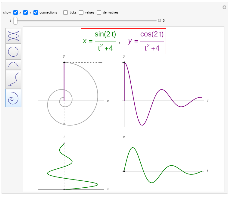
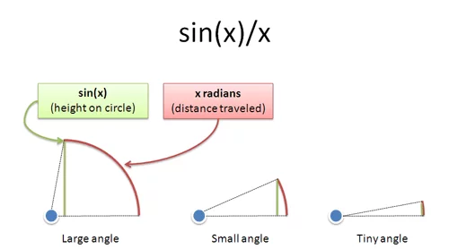
(MATHEMATICS WARNING) If we want to really understand how things go from 2 seperate signals into 1 cohesive drawing we will need to understand a tiny bit of mathematics! Generally speaking if I have any kind of two dimensional surface and I want to draw some kind of continuous line in this surface over a period of time we will need to have two peices of information: Where are we in the X position at any given time and where are we in the Y position at any given time! In mathmatics when we want to think this way we call the curve a parametic curve and think about two seperate functions of time, x(t) and y(t).
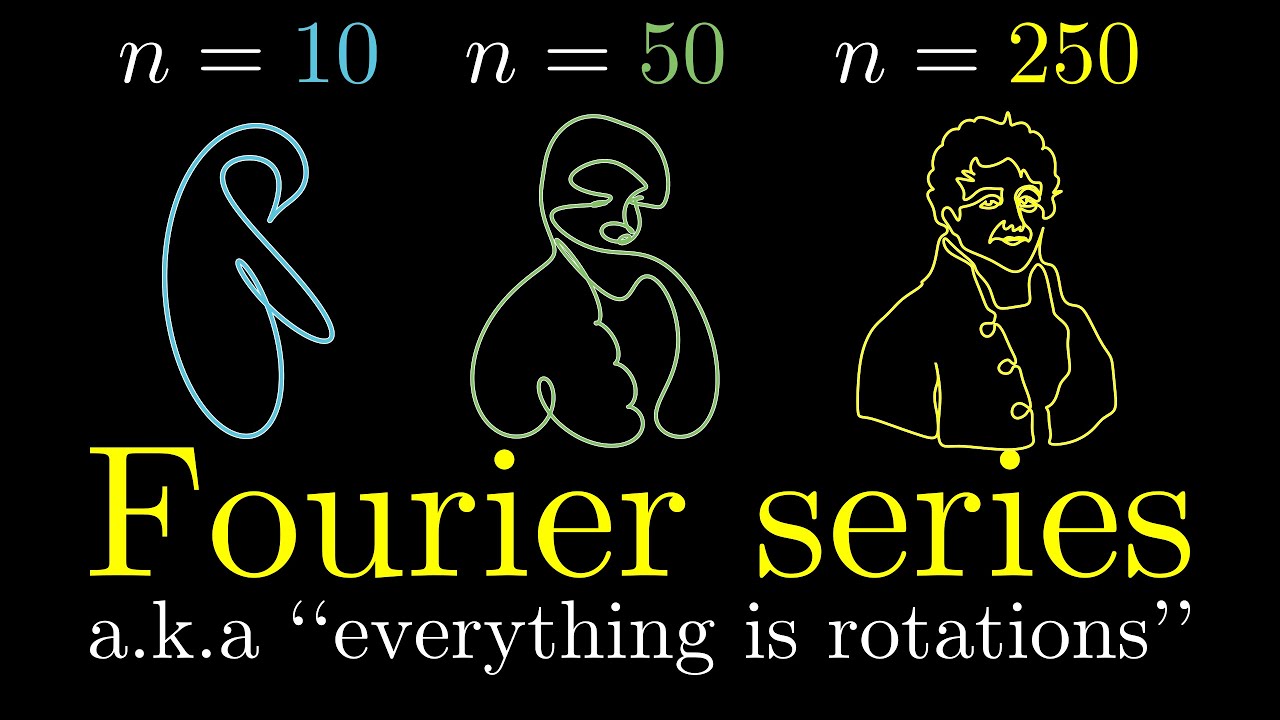
Also if we are using any kind of alternating current for our signals (audio can be considered a very specific kind of alternating current which is limited to rates roughly between the frequencies of 20hz to 20khz but we can go pretty far outside of these boundaries in either direction and still have a quite a bit of fun with vector synthesis!) then we have by the results of Fourier (well it was really one of the Bernoullis that first worked this out but not quite as well as Fourier did, plus the Bernoulli numbers were really discovered by Faulharber so it all evens out at some point) that we can just think about any oscillation as being accurately approximated by a sum of sine waves so without any loss of generality we can ignore all the other potential wave shapes out there and just talk about sines.
Thus we have that we can generally think of the two seperate signals going into the oscilloscope as being
x(t) = A_x(t) * sin( f_x(t) )
y(t) = A_y(t) * sin( f_y(t) )
respectively, where A_x(t) is the amplitude of the x signal at time t, f_x(t) is the frequency of the x signal at time t, and same diff for the y sides of things. Lets now throw away the more confusing notational things and just say
x =A*sin(t)
y=A*sin(t).
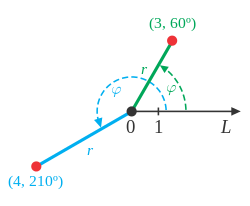
When we represent a parametric curve in terms of sines and amplitudes we call this the Polar Notation. In mathematics we use polar notation for certain curves that would otherwise be obnoxious, tangled, or cumbersome to write down and calculate with using just plain old algebra. We will find that this family of curves is pretty much exactly what we want to think about when we are doing Vector synthesis.
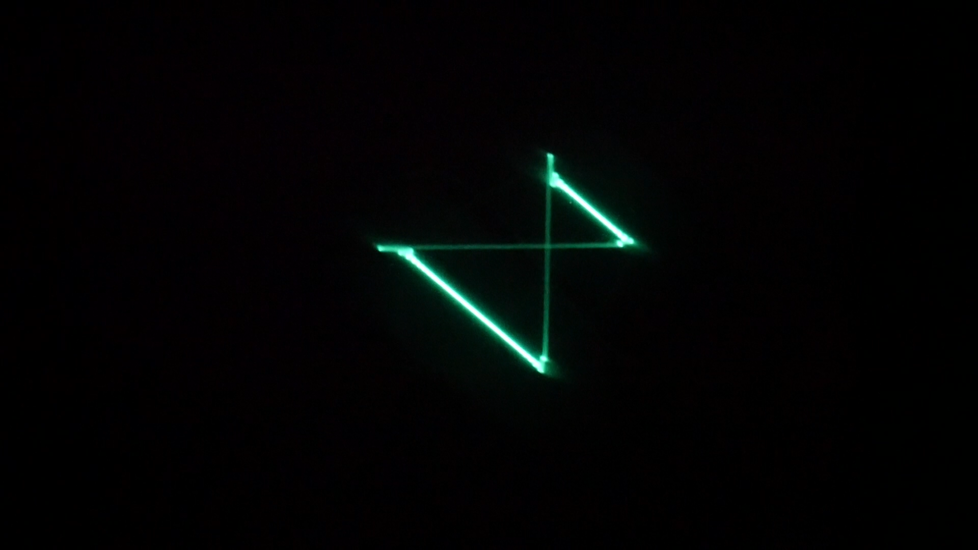
So lets say i have two sine wave oscillators set up so that each is running into the x and y inputs of an oscilloscope set to vectorscope mode. Both x and y oscillators are running at the same frequency and amplitude. What will I see when i turn on the scope?
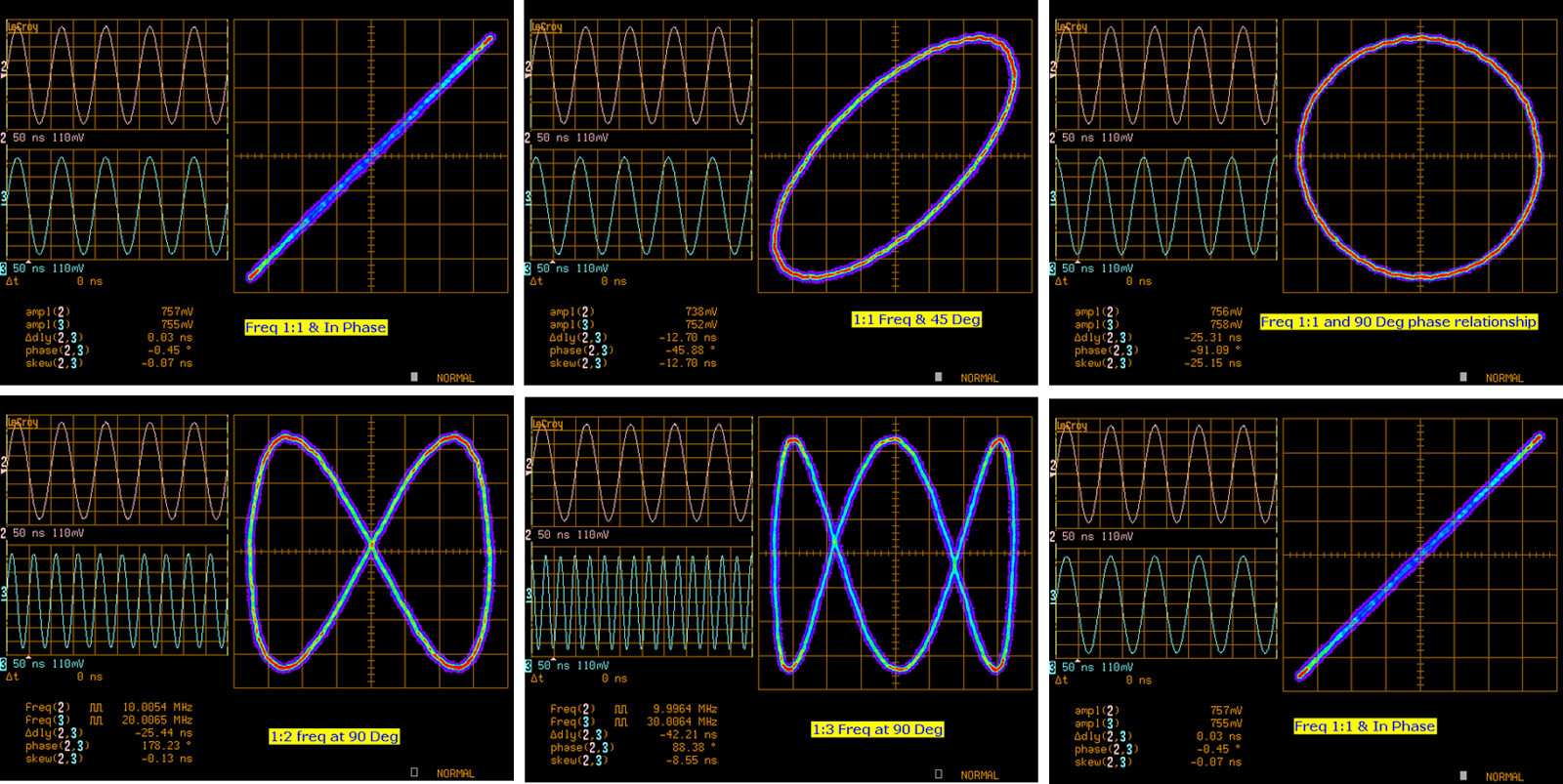
A diagonal line! This is a pretty boring curve! How do I spice this up a bit? I thought I would be seeing some kind of shape like a circle or maybe one of those pretty lissajous curves! Ok so I take the y oscillator and start to add a phase offset P to the argument so that I’ve got
y=A*sine(t+P)
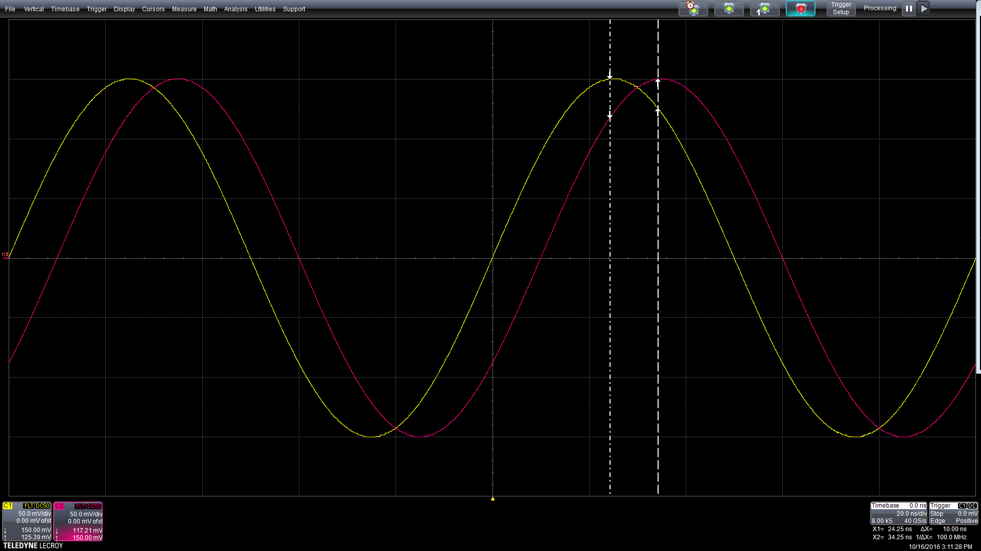
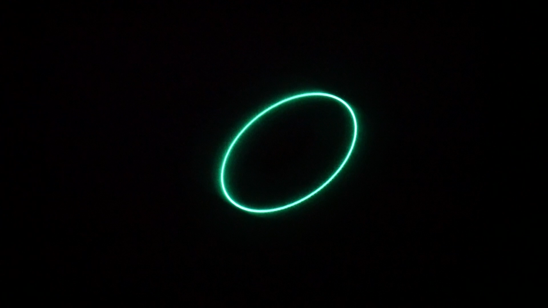
As I increase P from 0 on upwards to about 1 1/2 or so I see something interesting happening! The diagonal line starts to fluff out and becomes an ellipse that expands into a circle right near like 1.57 ish! This is getting a bit more interesting!
Whats going on at 1.57ish? This is a rough approximation of PI/2. We don’t need to care too much about why this is happening rn other than just noting that if I have these two identical sin wave oscillators running it that have a phase difference of PI/2 then we get a circle! This phase difference is pretty much the important part to note here, the best results in doing vector synthesis result in making sure that our oscillators have some kind of phase difference happening otherwise the patterns won’t ‘bloom’ outwards and will instead curl up on the same line.
This is pretty much one of the main diagonstic reasons for engineers to use oscilloscopes in x-y mode! You can analyise very small phase differences in signals that might be otherwise difficult to discover by this method.
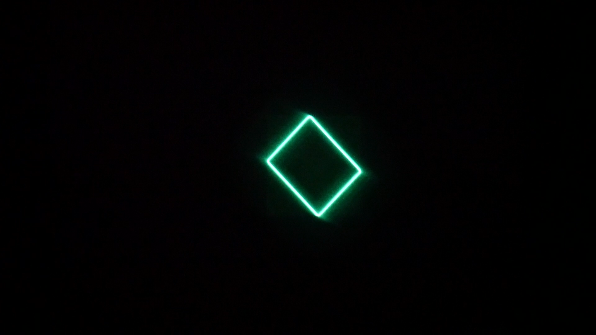
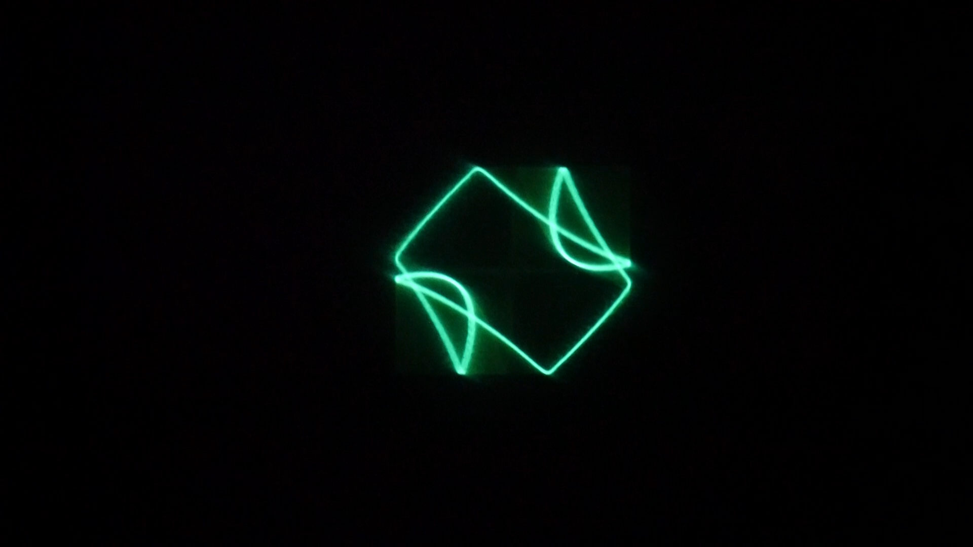
In a nutshell we have established enough information to understand what exactly is going on when we boot up Phosphorm plugged into a scope and/or CRT and see a circle on our displays! The default state of Phosphorm is that of two seperate sine wave oscillators hard panned to left and right channels and seperated by a phase offset of PI/2.
WHAT IS THE CONTEXT FOR THIS SHIT YO WHY ARE U SPITTING SO MUCH MATH AT ME ANDREI

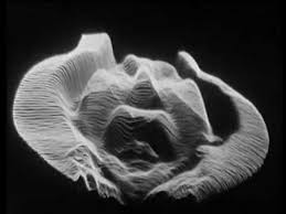
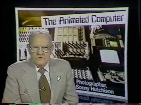
Lets step back from this engineering mathematics fourier biz for a moment and talk about why anyone would give a hoot about the applications of any of this stuff! This might be kind of surprising to some folks but it turned out that using various forms of vector synthesis was pretty crucial for certain special effects and animation techniques in the late 1960s up until vaguely the 1980s when microprocessors and RAM became cheap enough for digital animation techniques to become competetive for television and movie studios.
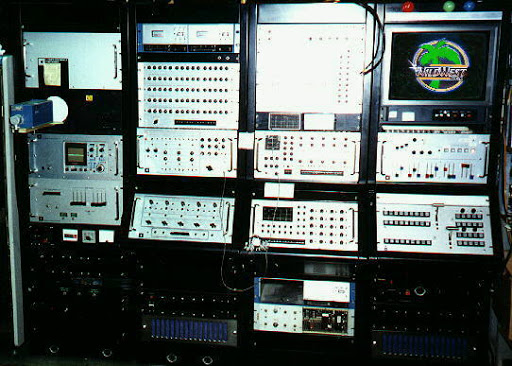
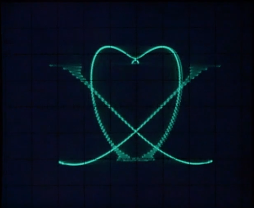
The most high tech animation system being used in this time was a sprawling system of analog computers, cameras, and specialized oscilloscope style displays known as Scanimate. This has been touched on over in my Spectral Mesh manual when I was going over the roots of Scan Processing so I will be glossing over some aspects of this massive system. The root of the system was: a special camera would take in some kind of footage from the external world and convert it into a black and white video signal. A scan proccessor would convert that black and white video signal into something you could feed into a special x-y (and z! but beyond the ‘scope’ of this current discussion**... {elliptical pause for laughter/groans/sounds of people navigating away}) oscilloscope display. The graphics on this display could then be modulated and warped using special oscillators set up essentially for doing vector synthesis but instead of just generating their own visible signals they could also be used to animate, warp, and deform incoming signals! The output from this would then be rescanned by another camera and run through a smooth and glossy 8 band colorizer that brought everything from wiggly greyscale lines on a tiny oscilloscope display into vibrant smooth animations!
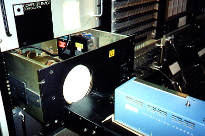
Of course as you could see from this description you would not necessarily need to have any video input to do abstract vector synthesis, you could simply plug oscillators into the display and then colorize them and you would be able to generate and control in real time all kinds of complex shifting shapes! For working with this kind of signal path I’ve also been developing a colorizer for the VSERPI system, stay tuned for more details on that. Given that any other animation techniques would require time to create each individual frame this was kind of a groundbreaking system! Not only that but by experimenting with different parameters on oscillators you could generate stuff you didn’t really expect or understand, nor did you even need to understand what was going on if you just wanted to tweak and play!
Of course the Rutt/Etra Video Synthesizer and especially its usage in the experimental works by the Vasulkas will be familiar to many folks. This peice of hardware was essentially just the scan processing brain from the Scanimate system but without the entire fucking room full of bespoke scopes and cameras and oscillators and colorizers etc etc.
Abstractions of this basic system for using oscillators into x-y displays and rescanning were, while not exactly common, still in some demand for television and film usage. Hand drawn animation studios were still a pretty big deal at the time but hand drawn animation was kind of suboptimal for doing something like say: a rotating 3 dimensional cube, or really anything that involved a lot of right angles, perspectives, and smooth rotations. Companies like OEI sold ‘3-d display display modules’ and then offer recipes for generating and animating basic geometrical shapes!

The Croatian born video artist Tomislav Mikulic, who was a bit of a polymath in analog and digital video art techniques, did some notable work using x-y scopes as well as more digital instantiations of vector synthesis concepts for various commercial and artistic projects. You can see from their youtube page that they also do a lot of work with x-y plotters which is essentially the same mathematics as vector synthesis! little bit slower tho lol
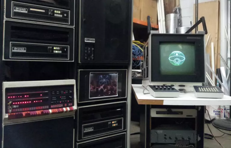
The seminal computer graphics artist Larry Cuba used Tom DiFanti’s GRASS visual programming language along with a Vector General to create vector animations for that one old ass Star Wars movie! This is notable as being one of the few Star Wars movies where people don’t seem to be viscerally infuriated by the computer graphics!
If you know of any more documents or information on the historical perspective (either artistic, commercial, or both!) of vector synthesis history please drop me a line at ex.zee.ex at gmail dot com and I can add them into this manual! This is definitely a work in process and I’d love to have as much context and links out there for folks looking to find out more about creative usages of oscilloscopes!
For folks active in modern day vector art I’d recommend looking into Albert Novello, Derek Holzer, Paloma Kop, Ivan Marusic Klif, Evan Henry, Andrew Duff, some of the many folks who have taken part in the Vector Hack Festival, and probably a ton more folks I’m omitting. Yes Jerobeam Fenderson does some pretty mind blowing stuff! But its all done by a vastly different process than what i’m talking about here so I’m not trying to snub them here but when you look more into their process (reverse engineered additive synthesis generated from visual information) you’ll see what I mean about how its not exactly vector synthesis in the process outlined above!
PHOSPHORM
Wow so now we have finally established some useful context for what the heck is going on with this Phosphorm thing! Lets delve into the inner workings of this bizarre little audio/video/vector synthesizer
OUTPUTS
So Phosphorm is been designed for using a variety of outputs simultaneously.
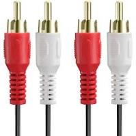
Via Rca cables we have the ‘audio’ signals (audio in quotes because these signals can potentially go above and below the audible frequency range but they exist in the standard line level audio format and travel via audio cables so ¯_(ツ)_/¯ ) which can be split via the provided rca passive splitters so one set can go into an oscilloscope’s x and y inputs as well as out into speakers or into whatever kind of sound processing chain you like!
If yr using a DAC edition the sample rate is 192k 24bit. If using the Basic Edition the audio does not actually have a sample rate or bit depth in the usual sense due to audio being converted to analog via PWM as opposed to more traditional DAC methods but you can think of it as being more or less 48k at 11 bits. The sound on these can get pretty wild and noisy so i recommend playing with delays, reverbs, filters, gates, etc for fun experiments. Yes passive splitters can reduce the overall amplitude of the signals but I didn’t want to involve active splitters in the versions I sell because of $$ reasons. I mess around with it via this exact set up all the time and it doesn’t harsh my mellow one bit.
And via Rca video cables OR hdmi cables (but not both at the same time) we can view a video output of a visualization of the audio signals as well! This means you don’t HAVE to have an oscilloscope to play around with the vector graphics with yr Phosphorm. Is this video output going to look exactly like what you’d see on a scope? Hell no! Can’t really be done, analog scopes run at Significantly faster rates and using fundamentally different processes that can only be emulated, not simulated via digital video processes. Its still cool and makes it way easier to get yr vector video stuff into SD video processing chains tho! The main use case for this would be using the video out and running it through some crazy fx and/or doing some ridiculous feedback on it! Try running through a Waaave Pool or Artificial Life for some real deal wild times!
Something to note regarding outputs of Phosphorm: All of the output signals for Phosphorm are generated using the same data structures. This means that there is essentially zero latency between visuals and audio. Pretty much only with this kind of transcoding based system is zero latency between video and audio possible! Latency, even in a tiny amount, has often been my frustration with
OSCILLATORS
Phosphorm has a lot of oscillators. In fact thats pretty much all that Phosphorm has! lots of oscillators. just oscillations oscillating more oscillations. an oscillofrenzy of oscilloinduldgent oscilloinsanity. Oscout Of Oscontrol.
One of the original sources of the concept for Phosphorm was that I wanted to make a system for synthesis that only used oscillators modulating other oscillators. This isn’t exactly the most ‘far out’ idea anyone could have, pretty much all of the Dx7 style ‘FM’ synths work this way. My hot take on this idea was that I wanted all of the oscillators to go from sub audio rate to supra audio rate so everything could either function as an LFO for control signals or as an HFO for doing amp/ring/phase modulation to generate complex waveshapes.
Lets introduce you to both the oscillators and my notation for thems!
osc_l1 is the primary AUDIO oscillator locked to the left channel
osc_l2 is the secondary AUDIO oscillator locked to the left channel
osc_r1 is the primary AUDIO oscillator locked to the right channel
osc_r2 is the secondary AUDIO oscillator locked to the right channel
Each individual ‘audio’ oscillator has another oscillator that is set up for amplitude modulation. Low frequencies of amplitude modulation result in tremelo. High frequencies of amplitude modulation result in new, complex waveshapes with all kinds of crazy harmonics being generated. Turning the amplitude of the audio oscillator down to 0 and amplitude of the amplitude modulation oscillator up to anything not 0 and you will see ring moduation instead.
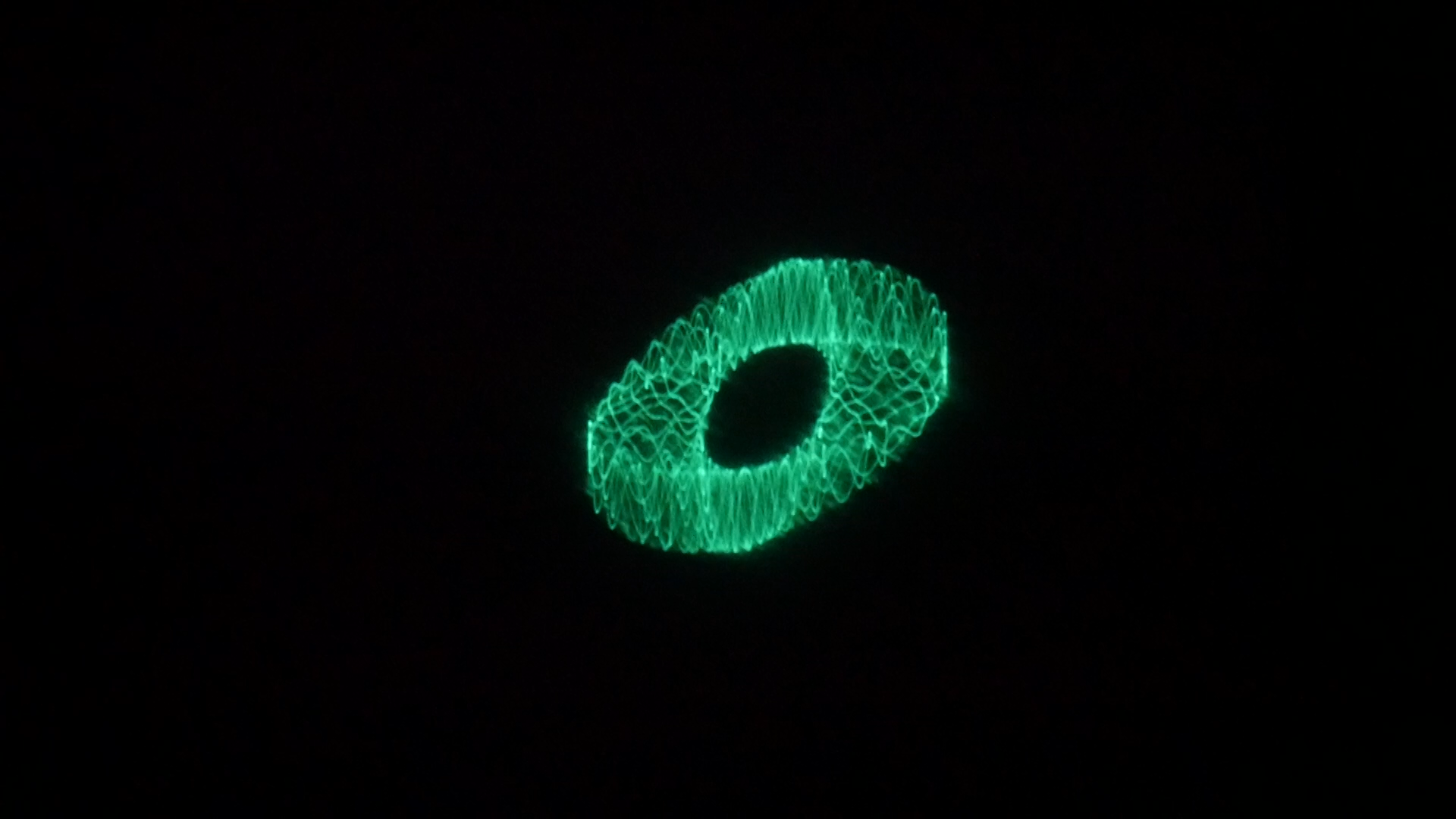
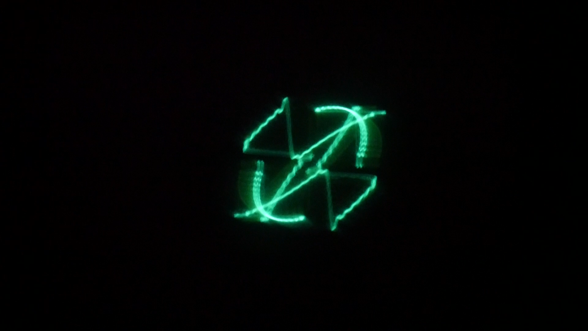
Loosely speaking, Amp Mod and Ring Mod are very similar except that Amp Mod preserves the fundamental harmonic structure of the Carrier (in this scenario the audio osc is the carrier) signal while Ring mod completely destroys the fundamental harmonic structure. Visually speaking you will notice that Ring Mod can be used to generate stellated shapes whereas Amp Mod seems to ‘embed’ another waveshape within the outlines of the carrier waveshape.
ampmod_osc_l1 is the oscillator that performs amplitude modulation on osc_l1
ampmod_osc_l2 is the oscillator that performs amplitude modulation on osc_l2
ampmod_osc_r1 is the oscillator that performs amplitude modulation on osc_r1
ampmod_osc_r2 is the oscillator that performs amplitude modulation on osc_r2


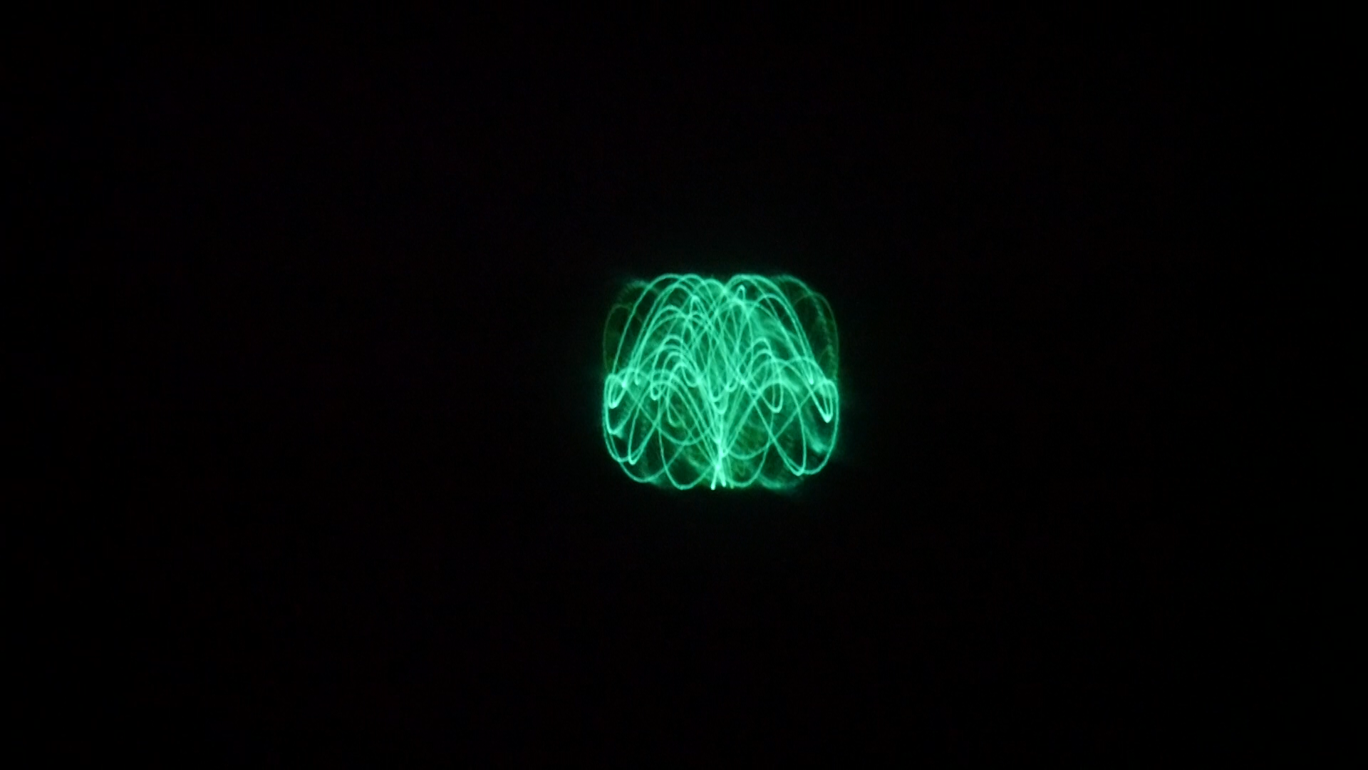
And finally each audio oscillator has another oscillator set up for doing phase modulation. At low frequencies the phase modulation oscillators will not do too much audible things to the audio oscillators but they will make the vector signals spin around the relevant axis! At medium frequencies the phase mod oscs will have a vibrato effect on the audio oscs. And at high frequencies the pmo (like how it gets shorter every time? i’m getting tired...) will generate complex harmonic structures! You have most likely seen or heard or worked with phase modulation in synthesis systems before as nearly every single synth that claims to do ‘FM synthesis’ is actually doing phase mod instead of frequency mod! This is for a reason tho, much like the situation with amp mod vs ring mod, phase mod preserves the fundamental harmonic content of the carrier osc while frequency mod obliterates it. I might say some misleading things to you about how an electron gun works (ok its deflection coils that aim the electrons the gun doesn’t move at all) but I Will Never Lie To You About Phase Modulation!!!! This is what seperates me from the Yamaha Corporation.
Waveshapes
Each oscillator has 3 basic waveshapes to choose from. The default for each is a sine wave, but with the press of a button you can change into Sawtooth or Triangle Wave. What no Square wave?!?! you ask in disbelief? Well I actually added in another feature that allows for all kinds of right angled waveshapes including but not limited to Squares!


Bit Crushing
Each oscillator is sent through a variable bit rate crusher. You can control how much the unquantized signal is mixed with the quantized signal as well as vary the bit depth from 2 bits (makes everything into squares and pulses) to 24 bits (allows for crunchy mild distortion and fun staircased waveshapes!).
Overflow
Each of the audio oscillators is set up to potentially go ‘out of bounds’ and be overdriven. At the end of the chain we have the ability to control what happens to these out of bounds signals.
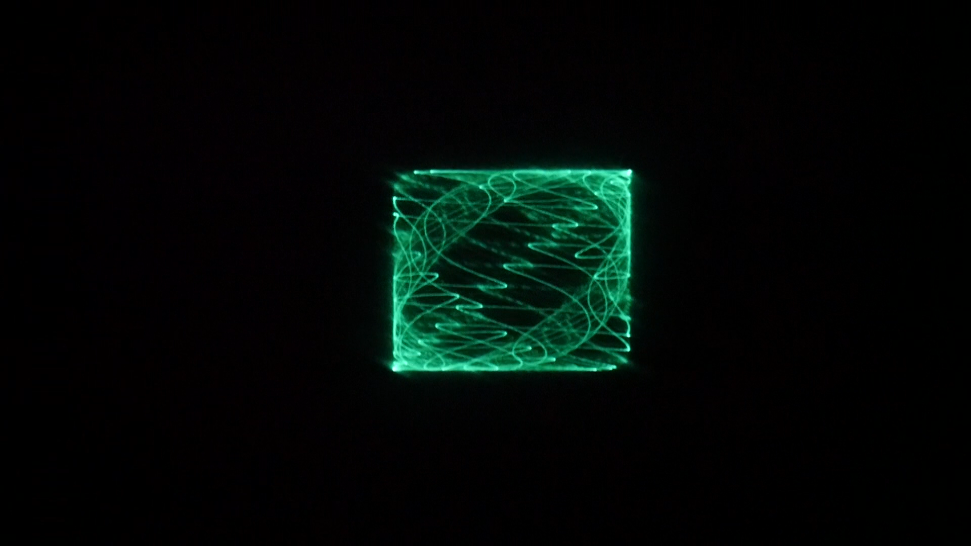
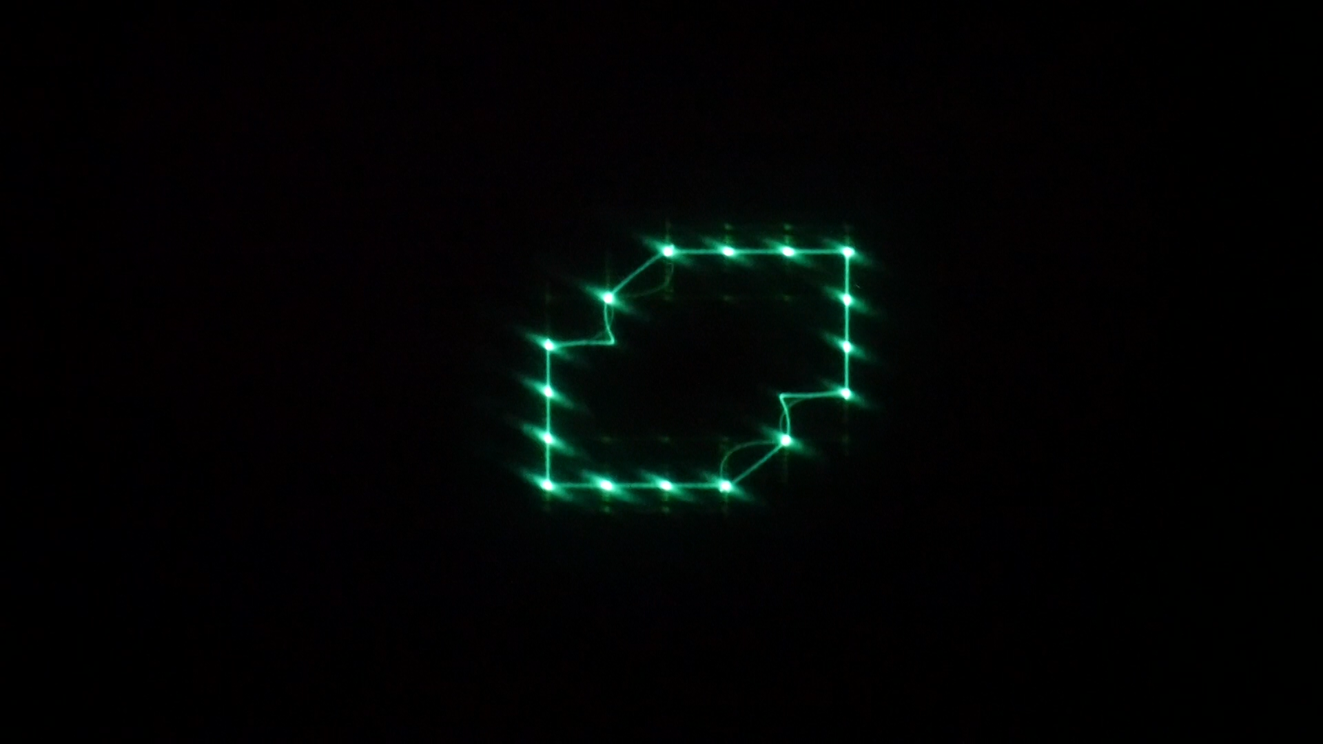
The default overflow setting is Clamp which means the signals just get hard clamped at maximum amplitude. This makes the output signals sound distorted and results in a clearly dilineated rectangular border in the vector images. This is more or less how overdrive distortion works in a very idealized manner.
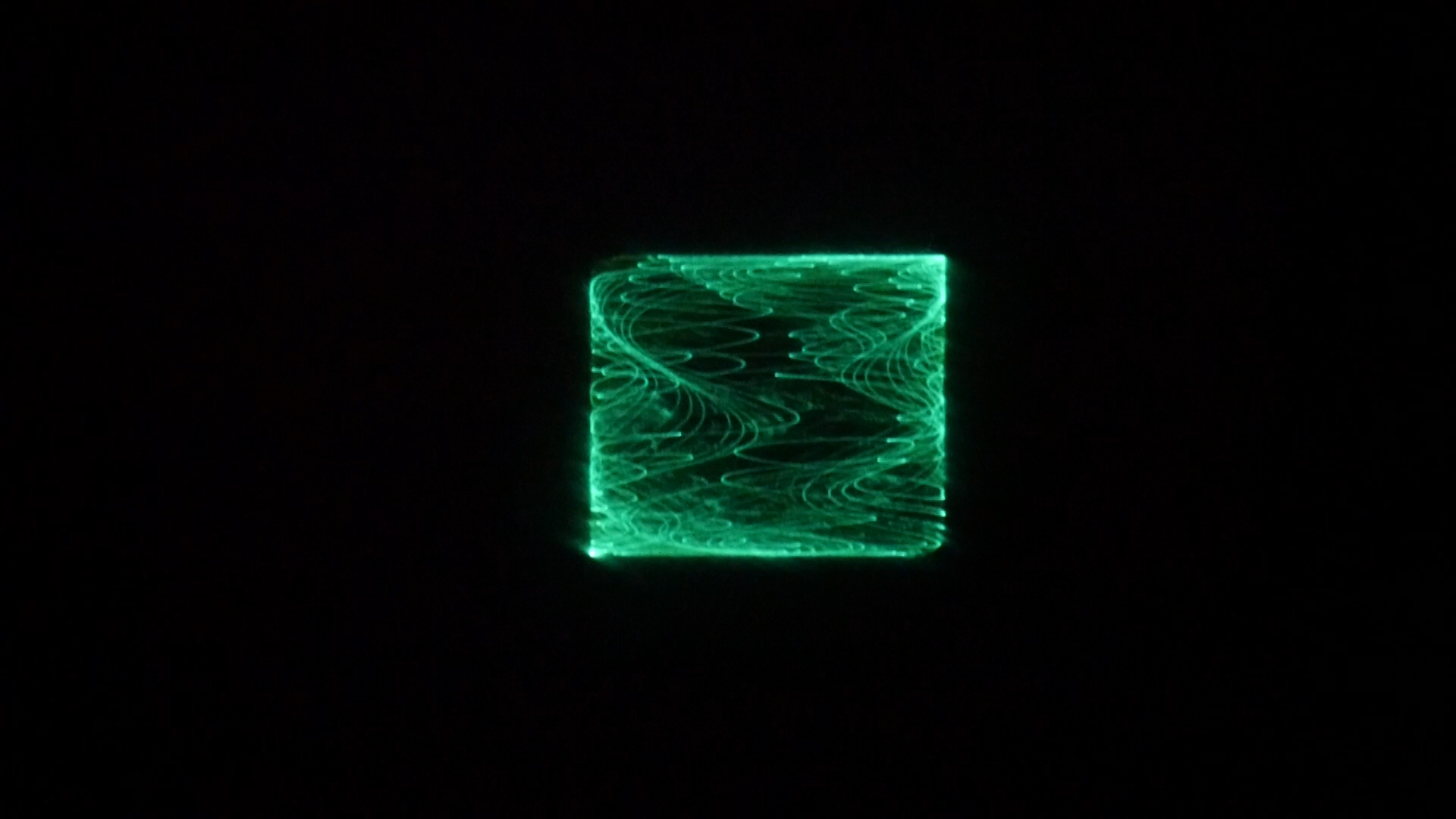
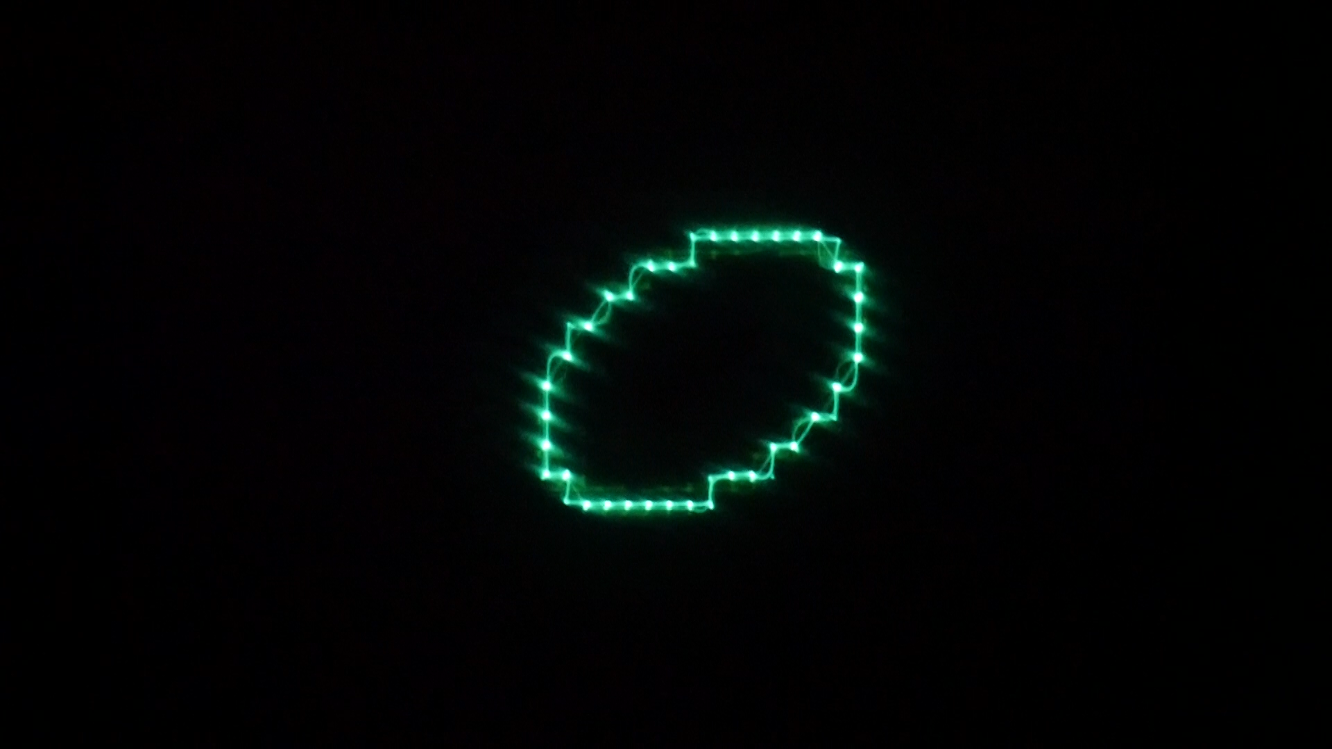
We can also select Wraparound which takes overdriven signals and wraps them around 0. This results in a lot of potentially atonal high frequency harmonics to be added to the signal and interesting discontinuous shapes in the vector images. You may be familiar with Wrap if you’ve ever used a Kurzweil synthesizer with the VAST system.
And finally we have Foldover which bounces the overdriven signals back in a continuous and inverted fashion. This can work in a very similar way to phase modulation in both the audio and vector sense but with a very distinct flavor of its own. You might be familiar with Wave Folding if you’ve ever played with Buchla synths or have some modular gear that performs this function!
SCALE QUANTIZATION
When I was beta testing this little beast, one of the first things folks asked for was to be able to choose how the frequencies of the oscillators get quantized to help out with making lissajous figures. Because I am also kind of perverse and enjoy challenging folks I added several scale quantisation options in but set the default to 5 equal tones instead of anything immediately recognizable to Western ears as harmonic.
5ET is a scale created by dividing the octave into 5 equal tones. This scale is similar but not exactly like the Balinese Slendro scale used in some gamelan orchestras.
7ET is a scale created by dividing the octave into 7 equal tones. This scale has a similar flavor to that of Thai Piphat scale found in thai classical music though of course the actual phiphat scale is more nuanced.
12ET is a scale created by dividing the octave into 12 equal tones. This is essentially what Westerners think of as being The Musical Scale and has its roots in some legends about famous bean hater Pythagorus.
Carlos Alpha is a scale with no repeating octaves. Instead this scale is based upon equal tone steps where the step is generated from dividing a Western scale minor third into 4 steps, round about 77.965 cents.
Carlos Beta is another scale with no repeating octaves. Instead this scale is based on equal steps generated by splitting a western perfect fifth into eleven equal steps, or round about 63.8 steps. Both of these Carlos scales were developed by synthesis legend Wendy Carlos and first used on their album Beauty in the Beast. Each of these scales was chosen out of many potential subdivisions of western musics standard triad harmonics because of the sheer depth of harmonic relations to be explored within. As you might expect there are some real wild secret lissajous hiding in these scales!
Non quantized is theoretically not a quantized scale. Of course, since phosphorm is a digital synthesizer its still definitely 100 percent quantized at some level, but it’ll be a lot less obvious to discover here with human ears. Fast scrolling throught the frequencies will display stepping in some forms but still in much smaller steps than 12ET. In this scale you’ll have to work a lot harder to get lissajous shapes and basic harmonies but the trade off is that there is a far wilder and more feral world of vector shapes to discover here...
MOTION RECORDING
Phosphorm, like all of the synths in the VSERPI family allows for motion recording for sequencing any and all of the parameters. When enabled, everything you do on the midi controller gets recorded to an 8 second long looping ‘midi buffer’ so you can do all kinds of automation and draw yr own lfo kinds of things with this feature.
PUTTING IT ALL TOGETHER
So you can see that with this fairly simple idea of Oscillators modulating other Oscillators we have nevertheless established a highly complex system for simultaneous audio visual synthesis.
Combining audio oscillators. I wanted to have 2 audio oscillators for each channel because there are certain things you can do with summed oscillators that can be a lot of fun on the visuals. Try extremely high frequencies for osc_l1 and low frequencies for osc_l2 to see the high frequency shapes getting wobbled around by the low frequency signals. Try dialing in harmonies or octaves between osc_l1 and osc_l2 to see what happens. Then try dialing in a triad with an octave using osc_l1, osc_l2, osc_r1, and osc_r2!
Using the ampmod oscillators: Try experimenting with low frequency ampmod waveshapes at various amplitudes along with the the bit crushing turned on at like 2-8 bits or so for Gating and amplitude sequencing. Try dialing in harmonies and octaves between the ampmod and audio oscs at higher frequencies and pay attention to what kinds of shapes you see. What our ears hear as harmony is a reflection of physical patterns existing in the audible pressure waves and it can be very elucidating to visual these structures while listening to them!
Using the phasemod oscillators: Try experimenting with medium frequency phasemod shapes at various amplitudes and with various settings of bit crushing to get quantized pitch sequencing happening! Try setting up slightly different settings for each of the audio oscillators with this same signal path for polyrythmic pitch sequencing. Then try recording some motions on the controller!
Once you get the hang of doing amplitude and pitch sequencing with the oscillators and bitcrushing then try doing some motion recording on the amplitudes and frequencies of the ampmod and phasemod oscs! You’ll find that even without a keybed involved there is a lot of room performative and compositional work with this synthesizer! It kind of drives me crazy sometimes how like nearly every single synthesizer out there only allows for either piano style input or some kind of grid based 16/32/64/2^n based sequencing. Are pianos and powers of two prerequistes for composition? I would beg to disagree.
PARAMETERS, CONTROLS, and MIDI CCs
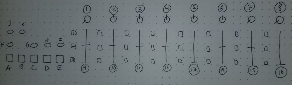
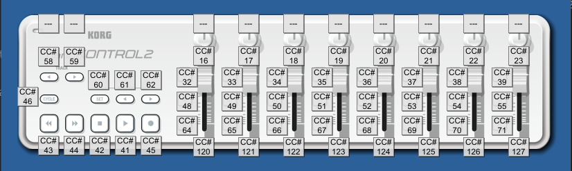
So you can see that theres only 16 continuous controllers here, seems implausible to have 12 oscillators controlled by this no? Well you can also see that there are a number of toggle switches adjacent to each slider. Pressing the S button next to each slider allows you to switch back and forth from the primary to secondary oscillator controls for each set of controls. I’ll be referring to each S button with the number of the slider immediately to the RIGHT of the toggle switch so S9 refers to the little S button directly to the left. For example here is the first set of controls.
1. Osc_l1_Amp [S9 Osc_l2_Amp] (0-2): adjust amplitude of Osc_l1 and Osc_l2. 1 (12 o clock noon) is the maximum amplitude possible for each individual Osc before overflow settings kick in. As Osc_l1 and Osc_l2 get summed together tho you can have overflow kick whenever the summed amplitude of both exceeds 1. Thus if I have Osc_l1 at 10 o clock and Osc_l2 at 9 o clock the overflow settings will kick in and you’ll see clamping, wrapping, or foldover!
9. Osc_l1_Freq [S9 osc_l2_Freq] adjust the frequency of Osc_l1 and Osc_l2. No I don’t know offhand what the frequency ranges are and they will be different depending on which scale you have selected! Assuming yr running this through a scope tho itsll be pretty easy to figure out!
M9 Osc_l1 Sawtooth: change the waveshape
R9 Osc_l1 Triangle: u get it. While either of these is pressed the waveshape will be whichever was the most recently pressed toggle. When you untoggle either of these the waveshape reverts to Sine.
M9+S9 Osc_l2 Sawtooth: When I write BUTTON +BUTTON that just means that both are active and lit, not that you have to press them at the same time!
R9+S9 Osc_l2 Triangle
So you can see that I’ll include brackets [] with the appropriate S button and a number to refer to Secondary Oscillator functions. I’m also going to group together all relevant controls for each set of oscillators to try and organize things from an operational perspective! I’m also not going to just cut and paste all that text stuff I just wrote up there to describe stuffs for the other oscillators, turns out that for example Osc_r1 and Osc_r2 work Exactly the Same as Osc_l1 so I have faith that u will be able to work things out if i just write
2. Osc_r1_Amp [S10 Osc_r2_Amp]
10. Osc_r1_Freq [S10 osc_r2_Freq]
M10 Osc_r1 Sawtooth
R10 Osc_r1 Triangle
M10+S10 Osc_r2 Sawtooth
R10+S10 Osc_r2 Triangle
Seems easy enuf no?
3. Ampmod_osc_l1_Amp [S11 Ampmod_osc_l2_Amp] (0-2) Adjust the amplitude of the ampmod Oscs for l1 and l2. Amp in this context refers to how strong or subtle the ampod Oscs affect the audio Oscs. Significantly different effects can be achieved by exploring differenc combinations of amplitude for each indivual Osc and amplitudes of their ampmod_oscs!
11. Ampmod_osc_l1_Freq [S11 Ampmod_osc_l2_Freq] Adjust the frequency of the ampmod Oscs. Individual frequencies will vary depending on what scale is selected. The frequency ranges were all tweaked for each individual set of Oscs for each scale to try and maximize useful frequencies. It can be particularly fun to slowly ramp up the frequency of one of these while viewing and listening to the output to discover what it looks and sounds and feels like when the ampmod_oscs hit the audible frequency range and move from tremelo into harmonic generation!
M11 Ampmod_osc_l1 Sawtooth
R11 Ampmod_osc_l1 Triangle
M11+S11 Ampmod_osc_l2 Sawtooth
R11+S11 Ampmod_osc_l2 Triangle
4. Ampmod_osc_r1_Amp [S12 Ampmod_osc_r2_Amp] (0-2)
12. Ampmod_osc_r1_Freq [S12 Ampmod_osc_r2_Freq]
M12 Ampmod_osc_r1 Sawtooth
R12 Ampmod_osc_r1 Triangle
M12+S12 Ampmod_osc_r2 Sawtooth
R12+S12 Ampmod_osc_r2 Triangle
5. Phasemod_osc_l1_Amp [S13 Phasemod_osc_l2 Amp] (0- like some number? dunno how to quantify this... numbers r kinda arbitrary in signal stuffs like this when u think about it. lets just ignore it for now. maybe its 0-1, maybe its 0-89, maybe 0- ᵞ ?) Adjust the amplitude of the the phasemod_oscs. Amplitude here can mean a lot of different things. At low frequencies this will control how much ‘spinning’ effect you see on the vectors. At medium frequencies this will control how much vibrato happens/how much pitch sequencing you can do! And at high frequencies watch out, this can get pretty noisey and crunchy! I do love the sound of gritty unfiltered phase mod synth sounds. Ever fuck around with those old yamaha toy FM synths like the pss series? that kinda sound! like 16 bits getting slammed through some old school cheapo DACs with that grungey cheapo amps? fun times
13. Phasemod_osc_l1_Freq [S13 Phasemod_osc_l2_Freq ]: Adjust the frequency of the phasemod_osc. As noted earlier, different frequencies will have way different effects in the process! I’ve like already written that part down like twice or thrice already tho and I’m like getting carpal tunnel over here.
M13 Phasemod_osc_l1 Sawtooth
R13 Phasemod_osc_l1 Triangle
M13+S13 Phasemod_osc_l2 Sawtooth
R13+S13 Phasemod_osc_l2 Triangle
6. Phasemod_osc_r1_Amp [S14 Phasemod_osc_r2 Amp]
14. Phasemod_osc_r1_Freq [S14 Phasemod_osc_r2_Freq]
M14 Phasemod_osc_r1 Sawtooth
R14 Phasemod_osc_r1 Triangle
M14+S14 Phasemod_osc_r2 Sawtooth
R14+S14 Phasemod_osc_r2 Triangle
7. Bitcrush mix Osc_l1 [M15 Bitcrush mix Ampmod_osc_l1] [R15 Bitcrush mix Phasemod_osc_l1] [S15 Bitcrush mix Osc_l2] [S15+M15 Bitcrush mix Ampmod_osc_l2] [S15+R15 Bitcrush mix Phasemod_osc_l2]
Adjust how much the bitcrushed signal is mixed with the uncrushed (?) signal. Ok Now Here it might get A Little Messy. I wanted to make sure that all the oscs were crushable which meant i had to get a little creative with the buttons here. IF S15 is NOT PReSSED and Glowing then pressing M15 means that the bitcrushing controls are for Ampmod_osc_l1 and pressing R15 means the bitcrushing controls are for Phasemod_osc_l2. If S15 is glowing then that means that M15 and R15 switch over to Ampmod_osc_l2 and Phasemod_osc_l2 respectively? Make sense? same shit for all the bitcrushing controls. Bit of a notational nightmare but hey once you work with it a couple times you won’t need to look at this nonsense anymore.
15. Bitcrush depth Osc_l1 [M15 Bitcrush depth Ampmod_sc_l1] [R15 Bitcrush depth Phasemod_sc_l1] [S15 Bitcrush depth Osc_l2] [S15+M15 Bitcrush depth Ampmod_osc_l2] [S15+R15 Bitcrush depth Phasemod_osc_l2] (1-24)
Adjust the bit depth of the crushing. 1 is 1 bit of resolution (meaning that the oscs are basically all square or pulse waves) and 24 means that you’ve got a 24 bit audio signal which will be visible as slight staircasing on the scope and a pleasant bit of mild distortion on the signal. Heads up that low bit depths result in sounds that can feel much louder than their non bitcrushed versions at the same amplitude. This is because quantizing and adding right angles in a wave form results in a higher frequency components being added to the harmonic structure. It can be a bit tricky to identify harmonic content from a wave form (for example if you have supercollider or something open, try generating a square wave from additive synthesis principles using a cosine wave and then a sine wave and compare the wave shapes. Radically different shapes, identical harmonic content!) but this is always a good rule of thumb. The coarseness of the quantizing is reflected by the range and distribution of the higher frequency components. Under 24 bits many folks interpret this as having some nostalgic chiptunish qualities. Once u start to quantize above 24 the teeny tiny little steps result in more subtle and potentially frustrating high pitched buzzing sounds on the Oscs. This is why a lot of modern Soft Synths can have sort of an annoying timbre in their Saw/Square tooth sounds unless they are set to Oversample at a high enuf rate that the quantized hf steps start to buzz higher than the sample rate will allow. This is also why a lot of overhyped ‘additive synths’ end up sounding like someone impersonating a cheap organ with a kazoo unless u spend like 2 hours on envelopes. This is why really low resolution additive synths can potentialy sound so much better, like for example the coincidentally named and highly recommended Phosphor!
8. Bitcrush mix Osc_r1 [M16 Bitcrush mix Ampmod_osc_r1] [R16 Bitcrush mix Phasemod_osc_r1] [S16 Bitcrush mix Osc_r2] [S16+M16 Bitcrush mix Ampmod_osc_r2] [S16+R16 Bitcrush mix Phasemod_osc_r2]
16. Bitcrush depth Osc_r1 [M16 Bitcrushdepth Ampmod_osc_r1] [R16 Bitcrush depth Phasemod_osc_r1] [S16 Bitcrushdepth Osc_r2] [S16+M16 Bitcrush depth Ampmod_osc_r2] [S16+R16 Bitcrush depth Phasemod_osc_r2] (1-24)
OVERFLOW
G: Wraparound Yo i think i explained this earlier? Just experimenting is really the best way to learn! Reading things is fun and helpful but there are more parts to yr brain than just verbal memories and true learning means engaging multiple levels beyond just the verbal aspect. You can learn a lot with yr hands that your words eyes can’t ever grasp.
H: Foldover: remember default setting is Clamp and to return to this mode just turn either of these switches off.
SCALES
A: 7ET
B: 12ET
C: Carlos Alpha
D: Carlos Beta
E: No scale in particular
and remember that the default scale is 5ET and can be returned to by toggling any one of these activated switches to off. if you skipped the part where i explained these scales in more detail, scroll up my friend.
MOTION RECORDING
I: motion recording on/off
J: parameter reset/motion recording clear
Welp thats about it for now. Hopefully I’ll be able to add a lot more info to the history section and more pretty pictures to the phosphormier part but fuck i’m tired and folks seem really stoked to read this so i’m just hitting publish now. direct typos (and i’m dang sure theres a lot of them but the main typos i’m referring too are incorrect informations for parameters/controls) to ex.zee.ex at gmail dot com.
*no, contrary to wikipedias page on a mid 1980s marketing term, vector synthesis is not using a joystick to cross fade between different audio channels. Apologies and much respect to Dave Smith/sequential circuits (I mean beyond all the synths u have to respect anyone using the Cerebus Font) but using a joystick to crossfade is still just literally crossfading yo. unfortunately not too many folks other than holzer and the rest of the vector hack crew is out there skewing the google search results for this so shits a little confusing for folks searching for this topic atm
**scopes with ‘z’ inputs exist and are very fun to work with. The z inputs work by using the input signal to modulate the ‘brightness’ or ‘intensity’ of the beam which can add highly intentional levels of depth to the vector output. Heads up though, you will want to look into the voltage range and frequency range of your individual scopes z input for best usage, its not always the same for every models and sometimes line level (a range of 0-2 volts) won’t be the most optimal signals to feed in. Phosphorm does not currently support z inputs natively but there are definitely some hacks for doing so for the more curious and experimental folks out there.

If you appreciate the public domain open source software and educational materials I provide and can afford to spare some cash it is highly appreciated! The more donations I recieve the more time I have to spend on developing these resources! Please also consider subscribing to my patreon page as small amounts of regular income are appreciated as well! Or you could also support my ko-fi if you like getting stickers and stuff on a regular basis.