SPECTRAL MESH MANUAL
Hello and welcome to the Spectral Mesh. The Spectral Mesh is a video resynthesizer designed for the Waaave Pool platform and inspired by scan processing video synthesizers of the past. Note: this manual is now updated for the 1.3 version released 5-7-2020, check out the github page for the download if you would like to update your version and this video for some visual explanations of how the updates work!
What is Scan Processing?
The first scan processing video synthesizer I am aware of was a crucial part of the Scanimate system. The Scanimate was a sprawling analog computer system that consisted of a signal path like such.
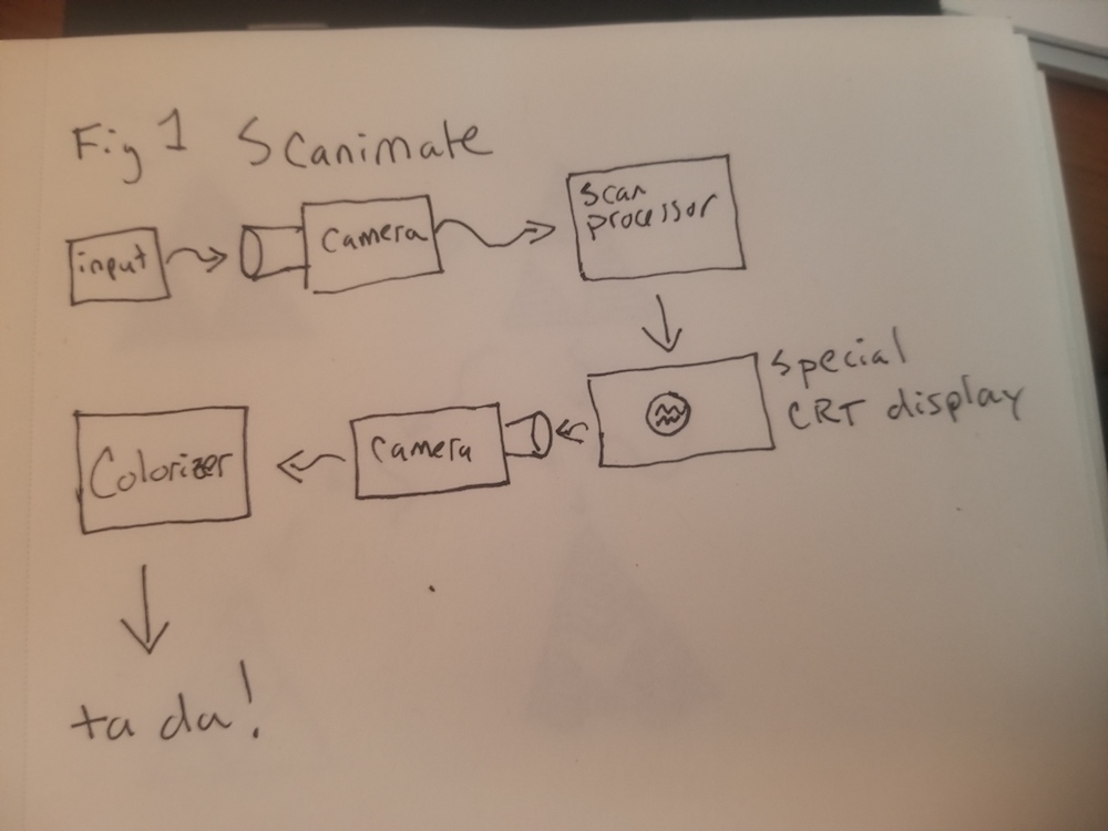
Note that the best methods available for getting images and video from each system at the time were simply pointing a video camera at a source! This low level solution to the capturing problem is still a useful tool for modern usage in certain cases e.g using a digital camera to rescan off of an analog screen for getting the analog signals into digital zones and using an analog camera to rescan off of a digital screen to get digital signals into analog zones! If you do some research on how ADCs and DACs function and how light waves, displays, and camera sensors function you can figure out for yourself what advantages the camera rescanning methods of signal conversion might have for specific usages especially with regards to speed and resolution.
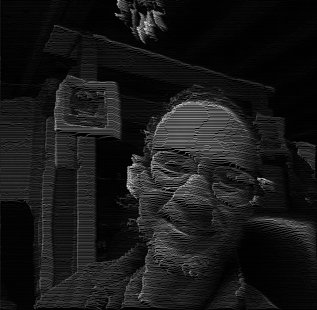
We will ignore the colorizer aspect of the Scanimate for now (although I am at work on a colorizer unit for the Waaave Pool platform so that folks can try to make their own low budget Scanimate style systems at home!) and focus on the scan processing. What this scan processing did was convert the black and white video signal from the rescanning camera and turn it into a series of horizontally space greyscale lines in a format for a special little cathode ray display that operated more like an oscilloscope than a television. (I will be skipping over and fudging a lot of details in these descriptions here just so yalls know. I do not want to get lost in the mechanics of this specific system but am more focused on the abstraction of the signal paths that are relevant to how the Spectral Mesh was designed. If you do want to get lost in the mechanics then Dave Siegs website is a great place to start!)
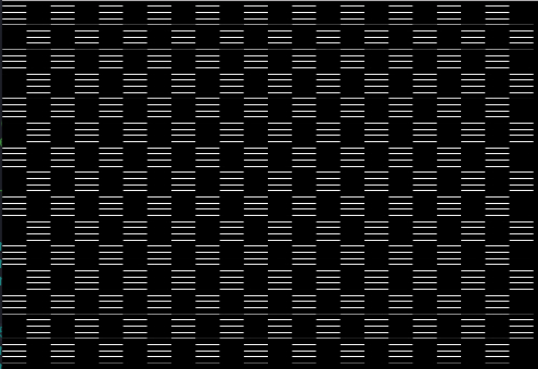
This would be kind of nifty on its own but like not exactly a multipurpose tool no? Well one of the details I fudged over just now is that when the video signal was converted into horizontally spaced lines it also converted the signal into something you could displace in x and y space with oscillators like so!
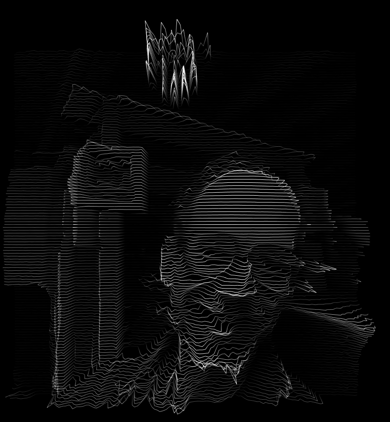
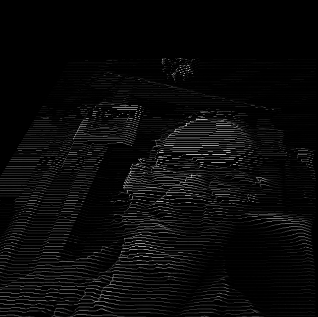
Not only that but you could also use a video signal to displace the horizontally spaced lines as well! I think most folks who are familiar with the concept of scan processing synthesis are probably primarily aware of this specific technique indirectly though examples of the work of the Vasulkas who utilized the Rutt-Etra video synthesizer, or perhaps through the Dave Jones Raster Scan which is still in operation over at Signal Culture or via many of the various Rutt-Etra Video Synthesizer software emulators available!**

Note that if you've worked with any of the Rutt-Etra software emulators before you may have noticed that there is nearly always a different kind of displacement perspective being utilized in the software style of emulation vs the actual displacements in the original scan processors. In the original analog signal path scan processors one really could only work directly with x and y displacements. By displacing an image in x and y with its own brightness values you would have a perceived effect of something very similar to isometric perspective (technically speaking it would only be isometric if x and y displacements are equal but the qualia of this process even when x and y are not equal seems fundamentally distinct enough to mentions). Most Rutt-Etra software emulators are written in a high level graphical coding language where folks have access to x y and z coordinate systems. Since most folks tend to perceive simultaneous movement in x and y as movement in z space (see parallax) and since it is a bit simpler in those coding languages to just assign brightness values to z displacement you end up with something that looks something like This
(via https://airtightinteractive.com/demos/js/ruttetra/
)
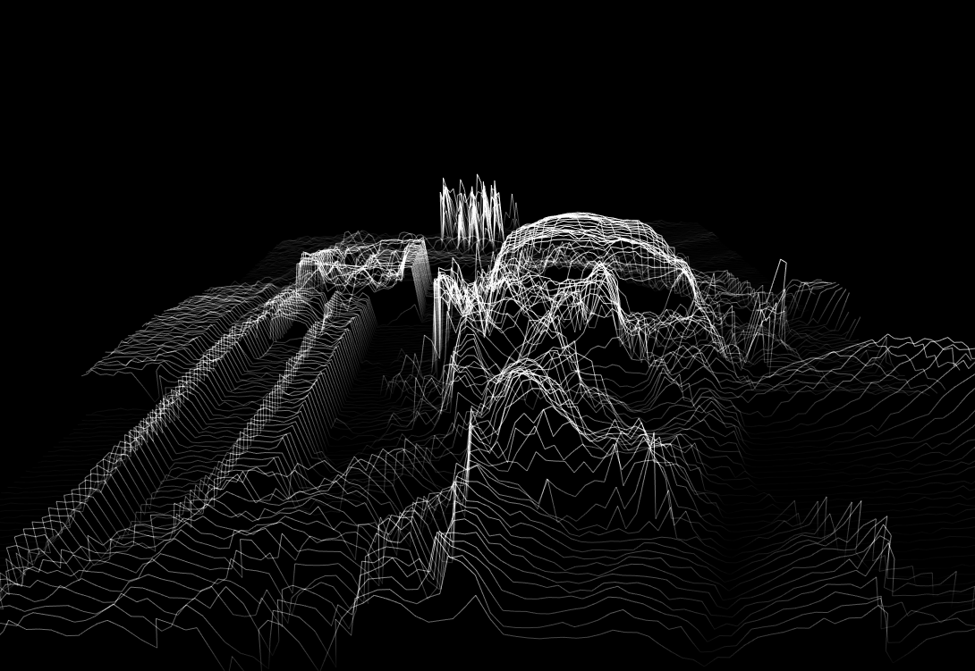
There are bonuses you get when working with this direct Z displacement method in digital zones, as you can see if you rotate the displaced image you get a really nifty landscape style thing happening!
Whereas if you rotate the x y displaced image in the Spectral Mesh in the same manner it becomes apparent that the perceived z displacement was only an illusion
For the moment the Spectral Mesh only operates directly in x and y displacements. I am certainly interested in seeing if I can develop an alternate mode in which this kind of z displacement can be acheived as well so that you can rotate things and see the displaced video dancing as a strange landscape but I wanted to focus on strict x y space displacements at first because I feel that having that space to work in allows the user to do more complex and exciting things with very alien style perspectives. Isometric perspective does not exist in the physical world but it is remarkably easy to work with in the signal processing world and I think that video synthesis tools should be optimized for delivering unique and alien experiences. And also since there already exist multiple software techniques out there for performing brightness to z displacement in 3 space forced perspective mode and the only existing analog scan processor out there available for usage these days is the Dave Jones Raster Scanner at Signal Culture (and even then you still have to make it through their residency application process and have to be privlidged enough to be able to afford an unpaid residency) I wanted to focus on this side of things. And also its way easier to do this kind of shit in glsl because there isn’t *really* any z space happening in the digital signal processing sides of things either!
Why is this called Spectral Mesh?
Welp because this system is working with a GL primitive type called a Mesh. Basically all modern computer generated or processed graphics are created or processed using Meshes. And a Mesh is really just a list of vectors (pairs of points in x y space) and instructions on how to connect them together. When I found out about these datatypes pretty much the first thing I thought of was “huh i bet it’d be pretty dope to try some rutt etra shit happening on these” and so here we are and yes it is pretty dope!
VIDEO OSCILLATORS DIGRESSION
I would like to take a short moment to explain some unique terminology for discussing video oscillators because understanding the differences between these and audio oscillators will be very helpful for working with the Spectral Mesh. When working with audio oscillators the main parameters that you would be concerned with would be amplitude and frequency.
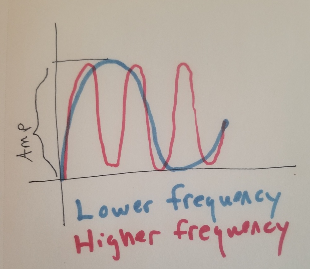
As you can see the amplitude is how high the oscillator reaches and the frequency is how often the oscillator oscillates for a fixed reference chunk of time! However this is a 1 dimensional signal and if we want to use a 1 dimensional signal in a 2 dimensional video world then we need to add another concept to the mix. Now we have to think about Frames!
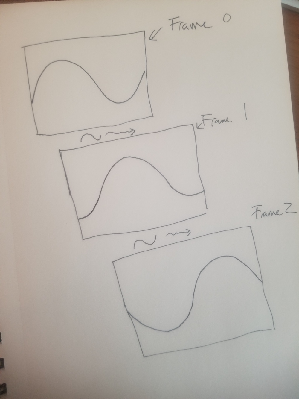
If we just use frequency and amp for our video oscillators then we have a issue where we can control like how many times per frame we have a drawn a full wave form but we can't control any kind of <-> movement of the entire chunk of waveform from frame to frame. So then we introduce a third parameter, Rate, which controls how many frames it takes the oscillator to oscillate!
and again I'm being incredibly sloppy and fudging a lot ofstuffs but i'm not even close to attempting to write a textbook manual on how video oscillators work, i'm just trying to give yalls some intuition on how the oscillators in Spectral Mesh work!
CONTROL SCHEMES
/***1.5 Updates Info****/
1. Luma Key Level (U) Luma Key removes portions of the input based upon brightness values. For example, if I turn my Luma Key Level knob to 12 o clock, that means everything in the input channel with brightness less than 50 percent will be removed. 0 means that everything is passed through, 1 means that everything is removed. When the luma key switch is flipped it just reverses the operation here so that if knob is at 12 o clock everything with brightness more than 50 percent will be keyed out.
2. Video Brightness to X displacement (B) (-200,200) This allows you to control how much the brightness value of the input affects X displacement measured in pixels. Brightness Alt Switch (G) changes this effect in a subtle way that is best illustrated just by trying it out.
3. Video Brightness to Y displacement (B) (-200,200) Same but for Y. I am curious how people feel about these ranges as well, please leave feedback in the fb group on if you enjoy these ranges as they are, if you would prefer that the ranges themselves follow the 4:3 aspect ratio, or if you would like them to be far larger or smaller than they are!
4. Z Lfo Frequency (U) Controls the visible frequency of the Z Lfo. See 11 for more info
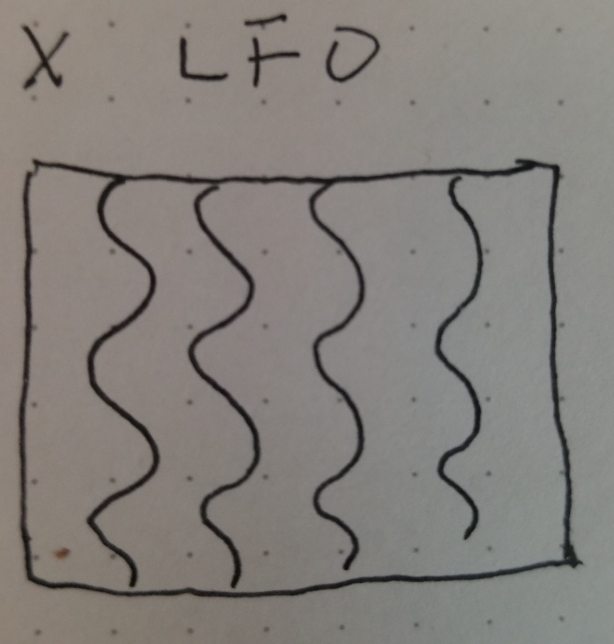
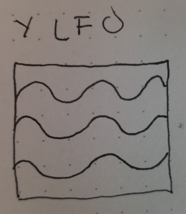
5. X Lfo Frequency (B) Controls the visible frequency of the X Lfo, see 13 for more info
6. Y Lfo Frequency (B) Controls the visible frequency of the Y Lfo, see 15 for more info
7. Global Zoom (B) Zooms the mesh in and about
8. Mesh Resolution/Line Thickness (U) (MAX,MIN)/(MIN MAX) The default setting for this knob is to control mesh resolution. This translates to both density of the lines/grids and to the resolution of vertexes on the lines and grids. When the knob is turned totally counterclockwise the mesh will be at maximum resolution and turning it to the right will decrease the resolution. Because recalculating the meshes is computationally expensive I could only afford to have them recalculated each time one of the Mesh Select buttons is hit (A,B,C,D). So in order to change resolution one needs to first twist the knob and then reselect the Mesh type using the Mesh Select buttons. There is a slight window after a Mesh Select button is hit where you have a couple seconds to fine tune the resolution before it becomes fixed again. When Line Thickness button is selected (E) you can additionally use this knob to dial up or down the line thickness. The specific use case this was designed for was to help with luma keying in video mixers.
//note! for the next two sliders I tried to cram a couple of multipurpose things into thems! So where it says like A/B/C and then (none, S, M) that means the slider does A when none of the nearby buttons is selected, it does B when S is selected, and it does C when M is selected!
9. Center X Displace/Global X displace/X Rotate (B) (none, S, M)
Center X displacement doesn't move the mesh at all in space but instead changes where the relative center of the grid in terms of how the LFO frequency is calculated. The best way to get a handle on this is to try dialing up all the Z LFO parameters and then shift this back and forth a bunch. It will affect X and Y Lfos as well but in more subtle ways.
Global X Displace: this will move the location of the mesh in X space.
X rotate: this will rotate the mesh around the X axis.
10. Center Y Displace/Global Y Displace/Y rotate (B)(none, S, M)
Same shit different axis
11. Z Lfo Rate (B) (PRETTY SLOW, FASTER , RING MOD, PHASE MOD) (none, S, M,R ) This controls the rate of the Z Lfo. Wait didn't I say something earlier about not using Z as a coordinate system? Welp yeah this version actually doesn't have any real Z biz happening, all that this is actually doing is like simultaneous X and Y displacments in like a ripple formation out from wherever Center X and Center Y displace (9 and 10) have deemed the center! Like if they are at (0,0) then itll go like This
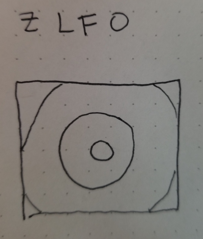
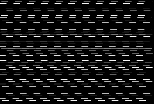
and say they are moved all they way over to like (- a bunch, - a bunch) itll be like This
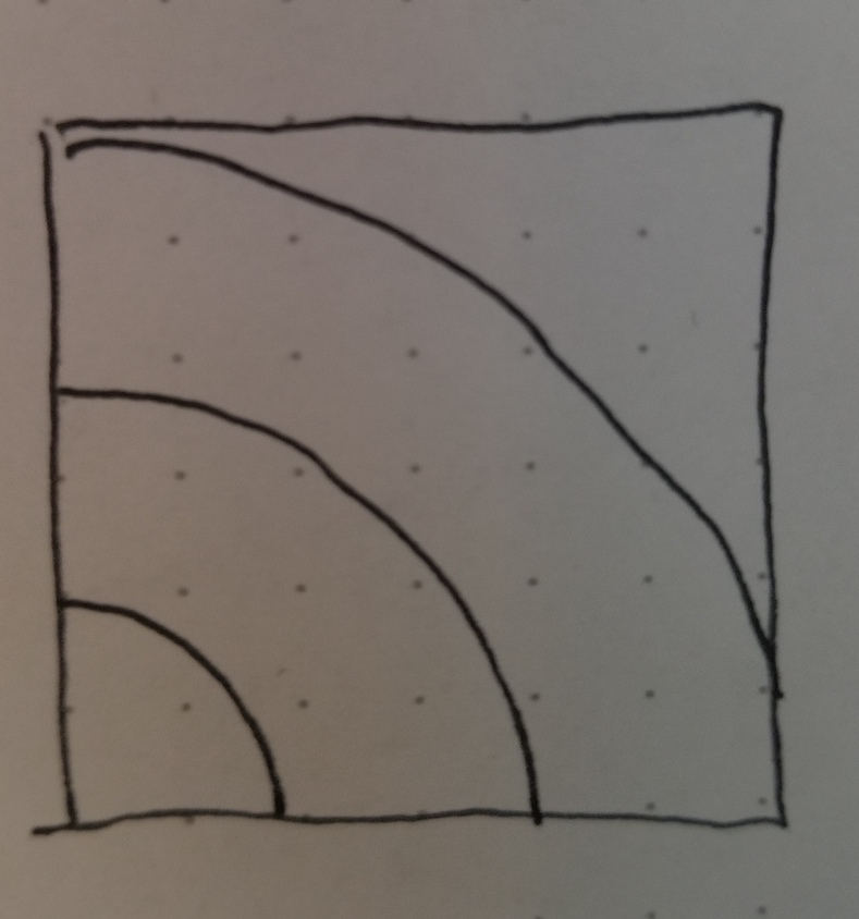
that makes sense right?
When RING MODULATION is switched on the Y Lfo will ring mod the Z lfo. Ring mod is bipolar amplitude modulation. Say we have signal 1 := Amp1*sin(theta1) as a modulator and signal 2:=Amp2*sin(theta2) as a carrier. To perform ring modulation in the Spectral Mesh we calculate a new signal (Amp2+Ampt1*sin(theta1))*sin(theta2). You can see that the new signal will have its total amplitude modulated at the rate and amplitude of the modulator signal. This is not strictly pure ring modulation but a pretty close workaround that makes it a bit easier and more fun to work with. Note that if we turn on ring mod and the Y lfo has no amplitude we won't see any effects. The words ring modulation actually come from the shape of the circuit design for implementing this in an analog realm in case you were wondering exactly what kind of mystical significance the ring has to this kind of modulation, though there may be some deeper Jungian ecstatic truth embedded within this terminology! The language of circuits is filled with obscure electronic poetry. Ring modulation is cascading through the oscillators as well, if we turn on ring mod on Z and on Y then we will have the X lfo modulating the Y lfo and then the modulated Y lfo will modulate the Z lfo!
When PHASE MODULATION is turned on the Y lfo will Phase Modulate the Z lfo. Say we have signal 1 and 2 defined as above. To perform phase modulation in the Spectral Mesh we calculate a new signal Amp2*sin(theta2+Amp1*sin(theta1)). You can see that the rate of the modulated signal will speed up and slow down at the rate of signal1 and at the amount of amplitude of signal 1. At low rates this will have the effect of a visual vibrato. Many folks are probably familiar in some way with a kind of audio synthesis which has been called FM synthesis thru the many implementations of Yamaha's patent of John Chowning's discovery (dxX hardware synths, sega genesis sound chips, plastic toy keyboards, the soundblaster audio cards omnipresent in pc hardware in the 90s). Fun fact, nearly everything Yamaha marketed as FM synthesis was actually PM (phase modulation) synthesis achieved via this same kind of basic signal path! Frequency modulation works very similar, just instead of adding the modulator signal you multiply instead like so: Amp 2*sin(theta2*Amp1*sin(theta1)).
The two kinds of modulation are very similar and essentially map signals into the same domain but have very different characteristics in terms of harmonics. If you remember anything from high school trig you can work out that Phase Modulated signals preserve the fundamental harmonic of the carrier signal while Frequency Modulated signals do not! This is essentially why true frequency modulation doesn't show up in synthesizers that often, it becomes difficult to write a catchy New Wave single or the soundtrack to Near Dawn with your fundamental harmonic going wiggly woggly all over the place!
This seems like an incredibly long and pointless digression. Thats because it kind of is. But also I am shoe horning my low key agenda that we should all stop calling phase modulation frequency modulation because hey, 1. We are all adults here, 2. Yamaha's patent has expired, and 3. The visible and audible effects of simple implementations of PM and FM are very different so lets just agree to throw out needlessly confusing misinformation from our discussion of synthesis and modulation techniques!
But yeah, just like in ring mod, the phase mod cascades as well, if phase mod is switched on for both Y and Z then the X lfo will phase modulate the Y lfo and the combined output from that will modulate the Z lfo! This is a pretty handy way to get a very wide range of dynamic effects from a very simple set of oscillators with simple sets of wave shapes.
12. Z Lfo Amplitude (B)
Controls how much displacement the Z Lfo does. The default waveshape of the Lfo is a sine wave, when S is selected it will be a square wave and M is selected its a Mmmmmm_delicious_Saw wave, and when R is selected it is a peRlin noise waaaave.
13. X Lfo Rate
yo same shit different axis
14. X Lfo Amplitude
Yeah same still
15. Y Lfo Rate
yup yup etc etc _fun bonus thing here, when you hit the R button next to this slider that alternates between different modes of calculating how the X and Y lfos interact! pretty nifty.
16. Y Lfo Amplitude
I have faith in you that you understand this by now.
Mesh Select buttons
So you may have noticed by now that some of these buttons work kind of funny. Yeah I know. One of my main goals with designing video synths was to have them be easily interchangeable on like a standardized model, sort of like how if you had some kind of nintendo you can just plug in different games and then play them but like most of the time you use the same controllers no? So yeah I went and designed the Waaave Pool and like made special midi schematic for it to use with either the default nanokontrol2 set up or with whatever kind of mappable midi controller folks would want to use. And then i went and designed the spectral mesh and realized oh shit, i turned every momentary switch over into toggles for the waaave pool set up and they work like fucking great over there and but then for this one is like oh dang momentaries for like almost everything would be better. so its kind of a weird trade off, i'm working on designing things around in the software sides of things to help over come the akwardness of this situation but until i figure something out like all this shit is still totally usable, just a little wonky is all! But yeah the main wonkiness you will notice on like all of the butons is that when you hit on it turns red and that means that mode is selected for now like lets say B horizontal line mesh. Then you hit another button C vertical linemesh and it turns red and switches over to that one. then you say ok id like to switch back to horizontal mode and you hit that button and the red turns off and nothing happens. then you get confused and hit it again and the red turns back on and the mode is selected and yr like "ok andrei, what is this nonsense" and here i am telling you that "yes it is nonsense but like much nonsense it is happening for a reason (and like much nonsense its happening because of ITALICS backwards compatibility issues)". So yeah thats how they work. its like kind of weird for now but like i said, i'm still working on things, whenever i get a better solution its easy as all heck to update so just like chill out, mellow down, relax up and etc etc, it all still works is just gots to like press things twice. could be worse yalls could be menu diving!
A. Gridmesh Fleshed out
This maps the video onto a grid and then fills in the grid with all the video stuffs. This is one of the huge differences between this gl "scan processing" and the old school analog kind, is that you can have something that looks like its just a straight up video signal but then you hit up one of those lfos and it starts to get all wobbly and stretched out and is like Whoa
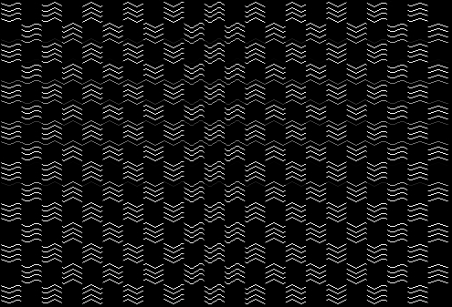
B. Horizontal Linemesh
This is like pretty similar to how the old school scan processors displayed stuff! but in color
C. Vertical Linemesh
This looks pretty dope, its kind of my favorite
D. Gridmesh totally Naked
same thing as A but the grids don't get filled in. Totally cyberpunk zones. Welcome to the GR1D
E. Line Thickness On/off
see 8 for more details
F. Monochrome switch. When this is switched on the output will be all shades of grey with alpha blending as well.
G. Motion recording
Turn on and off motion recording! When motion recording is enabled there will be an 8 second buffer that will record and loop all continuous input! Use this to sequence and automate every parameter to your hearts content!H. Alt Bright Switch
This affects how 2 and 3 displace the mesh, just give it a shot to see whats up.
I. HD/SD aspect ratio switch
For use with the Capture Bundle supported HDMI usb input, this will switch the aspect ratio of the captured video to support 16:9J. global Brightness invert
Globally inverts everything, helps if are trying to lumakey stuff into whites and/or just want to mix things up.
K. Parameter reset/Motion recording clear
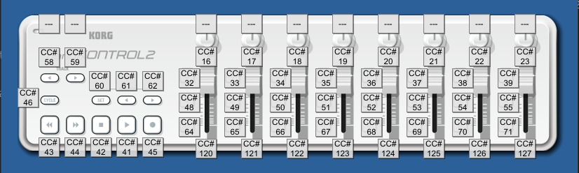
Resets all parameters to defaults and clears all motion recording.list of default midi ccs
Luma key -16
Video Brightness to X displacement -17
Video Brightness to Y displacement -18
Z Lfo Frequency -19
X Lfo Frequency -20
Y Lfo Frequency -21
Global Zoom -22
Mesh Resolution/Line Thickness -23
Center X Displace/Global X Displace/X rotate -120
Center Y Displace/Global Y Displace/Y rotate -121
Z Lfo Rate -122
Z Lfo Amp -123
X Lfo Rate -124
X Lfo Amp -125
Y Lfo Rate -126
Y Lfo Amp -127
***toggle switches***
Gridmesh Fleshed out -43
Horizontal Linemesh -44
Vertical Linemesh -42
Gridmesh Nude -41
Line thickness toggle -45
Weird Switch -46
key swap b/w -62
Alt Bright Switch -61
Center X Displace/Global X Displace/X rotate cycle (32,48,64)
Center Y Displace/Global Y Displace/Y rotate cycle (33,49,65)
Z Lfo rate cycle (34,50,66)
Z lfo waveshape select (35,51,67)
X lfo rate cycle (36,52,68)
X lfo waveshape select (37,53,69)
Y lfo rate cycle (38,54,70)
Y lfo waveshape select (39,55,71)
xAnd if yr using a usb keyboard heres the key map !
keyboard controls for each pair x/y means that the corresponding alphanumerical keys on a keyboard increment and decrement the values
a/z - lumakey value
q/w - Video Brightness to X displacement
e/r - Video Brightness to Y displacement
s/x - Z Lfo Frequency
d/c - Z Lfo Rate
f/v - Z Lfo Amplitude
g/b - X Lfo Frequency
h/n - X Lfo Rate
j/m - X Lfo Amplitude
k/, - Y Lfo Frequency
l/. - Y Lfo Rate
; / / - X Lfo Amplitude
[/] - resolution/line thickness
o/p - global zoom
t/y - Center X Displace/Global X displace/X Rotate
u/i - Center Y Displace/Global Y displace/Y Rotate
-/= - y skew
9/0 - x skew
1 - luma switch
! - resets all controls
2 - alternate brightmode
3 - global color invert
4 - weird switch
5 - z lfo waveshape select
6 - x lfo waveshape select
7 - y lfo waveshape select
8 - toriodal universe
9 - vertical linemesh
0 - horizontal linemesh
- - gridmesh fleshed out
= - gridmesh unfleshed
for troubleshooting tips check out the waaave_pool manual its all the same stuffs for this!
check out the Video Waaaves facebook group for info on this and other hard/softwares that I make! https://www.facebook.com/groups/440566853501750
**also many folks think that the album cover art for the famous joy division t shirt was generated using this technique as well. This was actually a spectral analysis of emissions from a star (fact check) and nothing to do with video synthesis. It is presented in an Isometric perpsective tho which i think has a lot to do with the confusion!

If you appreciate the public domain open source software and educational materials I provide and can afford to spare some cash it is highly appreciated! The more donations I recieve the more time I have to spend on developing these resources! Please also consider subscribing to my patreon page as small amounts of regular income are appreciated as well! Or you could also support my ko-fi if you like getting stickers and stuff on a regular basis.